Active Roll Control of a Transonic Rocket
Introduction
This project was developed for my capstone project (University of Michigan Aerospace Eng 405), by my senior design team: Nick Gloria, Jacob Johnson, Nicholas Ricci, Jared Shimoun, and myself. (Senior Design Paper)
The objective of this project was to design, build, and test a module to control and stabilize the roll rate of a rocket being developed by MASA. (Michigan Aeronautical Science Association). Our team produced and delivered a working prototype along with control algorithms to the MASA team in December 2016.

Flight Hardware
The roll control module was designed as an insert into the body of the MASA rocket. The module was assembled using a series of CNC cut 0.125 inch plates. An initial prototype was constructed out of balsa with allowances made for a future transition to sheet aluminum.


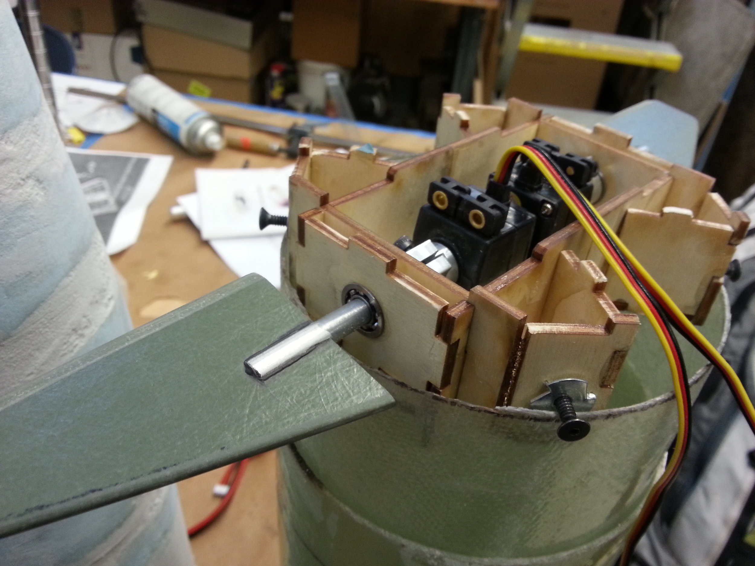
Test Hardware
Windtunnel testing for the roll control module was performed using a custom windtunnel fixture. The fixture was designed to simulate both the roll moment of inertia of the vehicle as well as the roll causing aero disturbance seen on the MASA rocket in flight. The inertia of the test subject was calibrated via sliding sliding masses as seen below. Aero disturbances were introduced by the addition of metal fins bolted onto the test masses.


Subsonic Testing
Subsonic testing was performed in the University of Michigan’s two foot wind tunnel. The video below shows the test subject with the control system both off and on. Controller gains were determined experimentally using this setup and then scaled to fit all subsonic flight regimes.
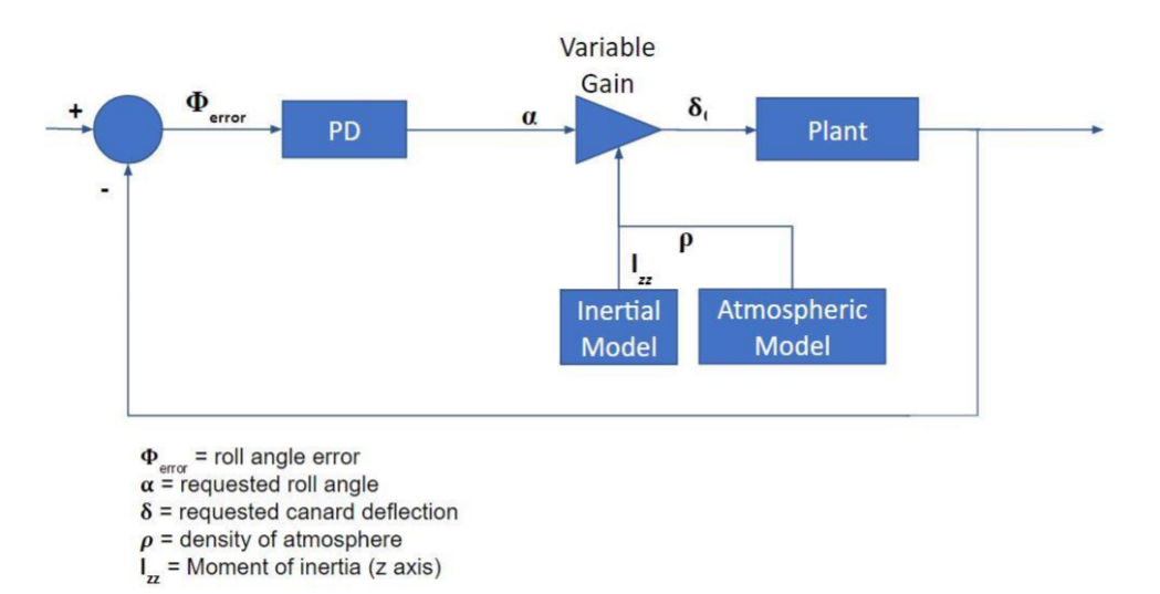
Control Algorithms
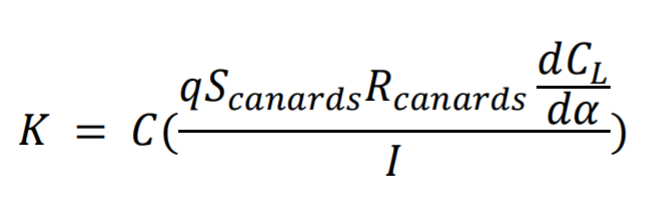
The controller for of module consists of a proportional and derivative controller with dynamically determined gains. Starting from our base experimentally determined gains, our gains are scaled up and down as the inertia of the vehicle, velocity of the vehicle, and density of the atmosphere changes. Gain scaling is done in an effort to hold the ratio of roll error to roll angular acceleration constant through all flight regimes.
q — dynamic pressure
S — canard aera
r — canard moment arm
dcl/ca — change in lift coefficient due to canard angle of attack
I — roll moment of inertia of the vehicle
C — Experimentally determined base gain
K — Gain for specific flight regime