Co-cure Composite Main Spar Design

Overview
I have designed, built, and flown the composite backbone, or main spar, for an SAE Aero Design competition advanced class plane. My spar encompasses theory from the classroom, industry experience, and real world test data from an iterative design process. The design has successfully met its given requirements and has been integrated into Michigan's 5th place competition plane.
Design REQUIREMENTS
The main spar has three major requirements: it must be able to withstand all bending and torsional loads with minimal deflection, it must be sectionable to allow for easy transport, and it must be built within a very tight mass budget.

Successful Static Test Loading

A Pinned Sliding Joint Allows for Bending and Torsional Load Transfer Between Sections
Design Overview
The spar is composed of three separable sections each clamped together using a pinned sliding joint. This joint allows for the transfer of both torsional and bending loads between sections. The cross section of the spar varies, starting with a wide rectangular prism at the root, thinning towards the tip of the wing, and then finally transitioning into an "I" beam at the the tip of the wing. The cross section changes to maintain a nearly constant safety factor of 1.5 in the midst of different bending moments across the wing. By designing the spar around a unified safety factor, I am able to achieve an extremely low structure mass. The end result is a 1.8 lb spar which successfully carries the weight of a 30 lb aircraft across its 15 foot wingspan.
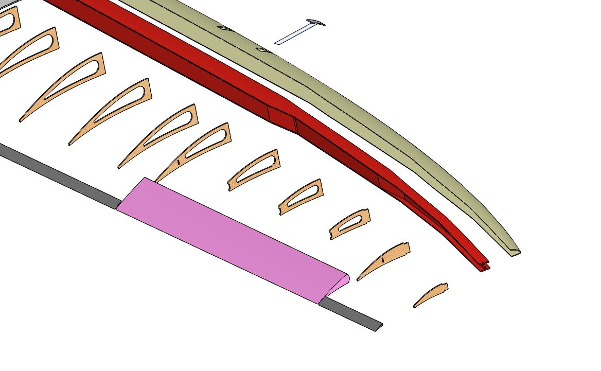
Exploaded View of the Wing, Main Spar Pictured in Red

Tooling and Fabrication
The three spar sections are produced separately, each using its own unique tooling. All three sections are produced as co-cure components with walls comprised of 1C1, 45 bias, 3k carbon fiber with vinyl foam core. For each spar, a wet layup is performed around an internal vacuum bag and then placed in the tool. The tool is then closed and an outer vacuum bag is placed around it. The inner and outer bags are then connected and the air between them is removed, forcing the laminate against the inner walls of the tool.
The outer thirds of the spar are produced with the addition of a small sacrificial wax plug. This plug creates a clean and precise internal surface which is necessary for the sliding joint.
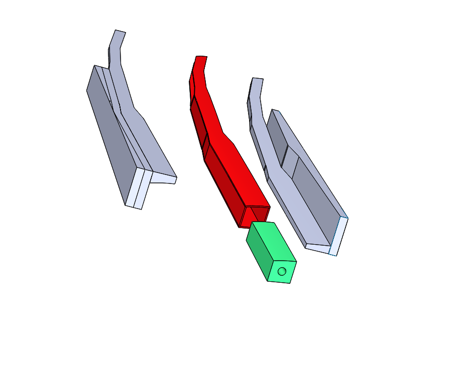
Outer Third Spar: Red Tool: Grey Wax Plug: Green
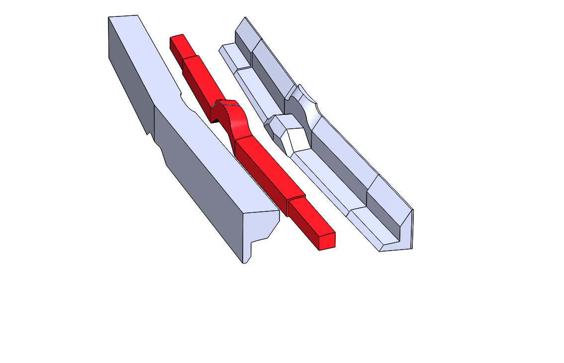
Center Spar: Red Tool: Grey